ASTM A350 Lf2 Flanges
ASTM A350 LF2 is a low-alloy steel, categorized for low-temperature service. It belongs to the broader ASTM A350 specification, which covers several grades of carbon and low-alloy steel forgings. ASTM A350 LF2 is particularly known for its balance of strength, toughness, and weldability, making it ideal for low-temperature environments.
India-based manufacturer of ASTM A350 Lf2 Flanges, meeting ANSI / ASME B16.5, B16.48, B16.47, BS 10, BS 4504, and EN-1092-1 specifications. Astm A350 LF2 flanges can be used at temperatures as low as -20 °F (LF1), -50 °F (LF2), and -150 °F (LF3).
Up to 1.65% manganese and up to 1% carbon are present in carbon steel A350 LF2 flanges, while other elements are present in amounts too tiny to have an impact on the material’s characteristics.
900–1200 °C is the forging temperature for SA350 LF2 flanges. Soak periods ought to be minimised to prevent severe scaling. However, the core needs to have adequate time to reach furnace temperature. It should be let to cool in steady air after forging.
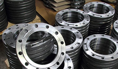
Flange WN A350 LF2 is widely used in the production of flanges and fittings, as well as in applications that call for cold temperature service and do not require corrosion resistance because to its mild strength and impact toughness.
Table of Contents
Any method can be easily used to weld blind flange lf2. This flange is devoid of both a hub and a bored centre. Its face thickness is comparable to that of a flange, and its bolting pattern and face type match.
The standard specification for forged flanges and flanged fittings made of carbon steel and low alloy steel for low temperature applications is flange material A350 lf2.
A350 LF2 pipe flange is a type of carbon steel that is often provided in one of three conditions: normalised, normalised and tempered, or quench and tempered.
Pipelines and forged flanges are the main applications for the A350 LF2 Class 1 flange.
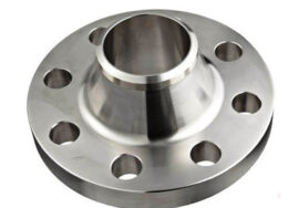
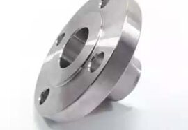
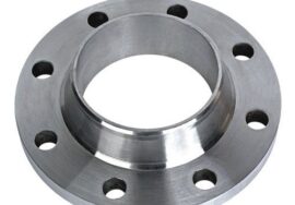
Depending on the condition, the a350 lf2 welding neck flange has extremely good machinability. Standard machine tool makers with required feeds and speeds can be used to expertly and satisfactorily perform operations like turning, sawing, milling, broaching, etc. It is made up of a circular fitting that has an elongating rim surrounding the edge. It is usually butt welded to a pipe after being machined from forging. A number of drilled holes in the rim enable the flange to be fastened to another flange using bolts.
ASTM A350 Lf2 Material Specification
| Size | 1/2" TO 4" |
| Range | 15 NB TO 100 NB IN 3000 LBS, 6000 LBS, 9000 LBS |
| Grade | ASTM / ASME A105/ A105N/ A694 F42/46/52/56/60/65/70 / A350 LF3/ A350 LF2 |
| Pressure Rating | 2000#, 3000#, 6000#, 9000# |
| Class | 150#, 300#, 400#, 600#, 900#, 1500# & 2500#. |
| Type | Socketweld Fittings, Screwed-Threaded Fittings |
| Form | Tee, Union, Full Coupling, Half Coupling,Elbow 45 Deg & 90 Deg, Swage Nipple, Cross, Cap, Plug Bush |
A350 Lf2 Carbon Steel Flanges Weight Chart
| Standard | Class | Diameter | Bolt Circle Diameter | Number of Bolts | Bolt Size | Diameter of Bolt Hole |
|---|---|---|---|---|---|---|
|
AS4087 |
PN14 |
95 |
67 |
4 |
M12 |
14 |
|
Table C |
95 |
67 |
4 |
13 |
14 |
|
|
Table D |
95 |
67 |
4 |
13 |
14 |
|
|
Table E |
95 |
67 |
4 |
13 |
14 |
|
|
Table F |
95 |
67 |
4 |
13 |
14 |
|
|
Table H |
114 |
83 |
4 |
16 |
17 |
|
|
Table J |
114 |
83 |
4 |
16 |
17 |
|
|
ASTM B16.5 |
ASTM 150 |
89 |
60 |
4 |
13 |
16 |
|
ASTM 300 |
95 |
67 |
4 |
13 |
16 |
|
|
ASTM 600 |
67 |
4 |
4 |
13 |
16 |
|
|
ASTM 900 |
121 |
83 |
4 |
19 |
22 |
|
|
ASTM 1500 |
121 |
83 |
4 |
19 |
22 |
|
|
ISO 7005 (DIN) Flange |
PN6 |
80 |
55 |
4 |
M10 |
M10 |
|
PN10 |
95 |
65 |
4 |
M12 |
14 |
|
|
PN16 |
95 |
65 |
4 |
M12 |
14 |
|
|
PN20 |
90 |
60.5 |
4 |
M14 |
16 |
|
|
PN25 |
95 |
65 |
4 |
M12 |
14 |
|
|
PN40 |
95 |
65 |
4 |
M12 |
14 |
A350 LF2 Blind Flange Thermal Properties
| Properties | Metric | Imperial |
|---|---|---|
|
Thermal expansion co-efficient (@0-100°C/32-212°F) |
10.4 µm/m°C |
5.78 µin/in°F |
|
Thermal conductivity |
21.6 W/mK |
150 BTU in/hr.ft².°F |
Carbon Steel A350 LF2 Slip On Flanges Chemical Composition
| Grade | C% | Mn% | Si% | S% | P% | Cr% | Ni% |
|---|---|---|---|---|---|---|---|
|
LF1 |
0.30 max |
0.6/1.35 |
.15/.30 |
.040 max |
.035 max |
0.30 max |
0.40 max |
|
LF2 |
0.30 max |
0.6/1.35 |
.15/.30 |
.040 max |
.035 max |
0.30 max |
0.40 max |
|
LF3 |
0.20 max |
0.90 |
.20/.35 |
.040 max |
.035 max |
0.30 max |
3.3/3.7 |
ASTM A350 Grade LF2 Class 2 Pipe Flange Mechanical Table
| Properties | Metric |
|---|---|
|
TS Min psi (Mpa) |
70,000 (485) |
|
YS Min psi (Mpa) |
21.6 W/mK |
|
EL (2″ Min) |
22% |
|
RA Min |
30% |
|
Hardness, Bhn |
Max 197 |
|
-50ºF Charpy |
Min Impact |
|
Energy F t/Lb (J):- |
Content
|
|
Set of 3 Specimen* |
15 (20) |
|
For One Specimen |
12 (16) |
Sa350 Gr Lf2 Forged Flange Pressure Chart
| TEMP °C | 150 | 300 | 400 | 600 | 900 | 1500 | 2500 |
|---|---|---|---|---|---|---|---|
|
-29 TO 38 |
19.6 |
51.1 |
68.1 |
102.1 |
153.2 |
255.3 |
425.5 |
|
50 |
19.2 |
50.1 |
66.8 |
100.2 |
150.4 |
250.6 |
417.7 |
|
100 |
17.7 |
46.6 |
62.1 |
93.2 |
139.8 |
233 |
388.3 |
|
150 |
15.8 |
45.1 |
60.1 |
90.2 |
135.2 |
225.4 |
375.6 |
|
200 |
13.8 |
43.8 |
58.4 |
87.6 |
131.4 |
219 |
365 |
|
250 |
12.1 |
41.9 |
55.9 |
83.9 |
125.8 |
209.7 |
349.5 |
|
300 |
10.2 |
39.8 |
53.1 |
79.6 |
119.5 |
199.1 |
331.8 |
|
325 |
9.3 |
38.7 |
51.6 |
77.4 |
116.1 |
193.6 |
322.6 |
|
350 |
8.4 |
37.6 |
50.1 |
75.1 |
112.7 |
187.8 |
313 |
|
375 |
7.4 |
36.4 |
48.5 |
72.7 |
109.1 |
181.8 |
303.1 |
|
400 |
6.5 |
34.7 |
46.3 |
69.4 |
104.2 |
289.3 |
417.7 |
|
425 |
5.5 |
28.8 |
38.4 |
57.5 |
86.3 |
143.8 |
239.7 |
|
450 |
4.6 |
23 |
30.7 |
46 |
69 |
115 |
191.7 |
|
475 |
3.7 |
17.4 |
23.2 |
34.9 |
52.3 |
87.2 |
145.3 |
|
500 |
2.8 |
11.8 |
15.7 |
23.5 |
35.3 |
58.8 |
97.9 |
|
538 |
1.4 |
5.9 |
7.9 |
11.8 |
17.7 |
29.5 |
49.2 |
|
TEMP °C |
150 |
300 |
400 |
600 |
900 |
1500 |
2500 |